Integrated Bottom Up Shade
A Step-by-Step Project Journal of Joe's Design, Fabrication and InstallationIntegrated Bottom Up Shade: Aluminum Extrusion Outer Frame
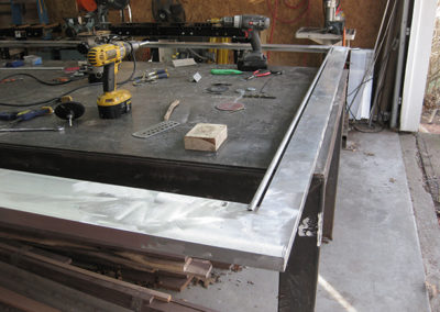
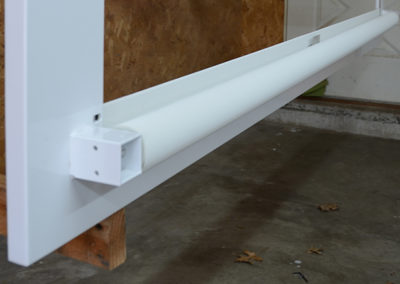
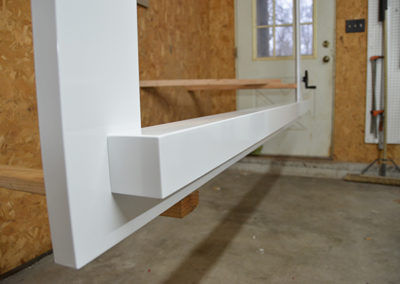
Our integrated bottom-up shade apparatus consists of an aluminum extrusion outer frame that contains within it all of the guts of the mechanism. This frame is just deep enough that it slips over the existing window frames. The goal is that the finished installation would look like it was part of the existing window system. Of course it is not. Here is pic of the basic aluminum extrusions welded together at the corners and the round aluminum tube shade guide installed. This guide is removable so the shade is very easy to install and remove.
Integrated Bottom Up Shade: Shade Roller Bracket
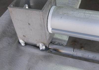
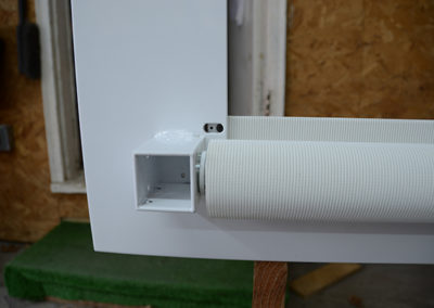
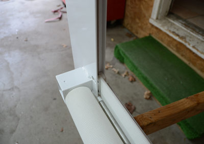
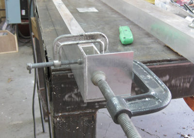
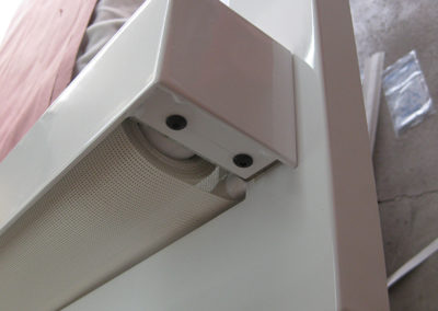
On one side the shade roller bracket is welded in place. The shade incidentally is a typical spring loaded roller shade. The only modification to the shade is that the clutch that engage/disengages the spring mechanism has been removed. The image shows the aluminum receptacles that the shade guide tube inserts into. By flexing the guide tube along its length it can easily be disengaged from these receptacles and removed. You can see in the pic how the shade is fed underneath the receptacle and enters a space where the guide track starts.
Integrated Bottom Up Shade: Removable Bracket
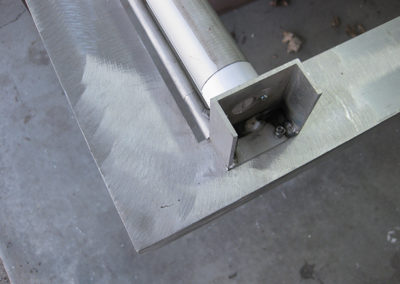
The other side of the shade tube is connected to a removable bracket. Taking this bracket out allows the entire shade and shade tube to be removed.
Integrated Bottom Up Shade: Simulating Install Conditions
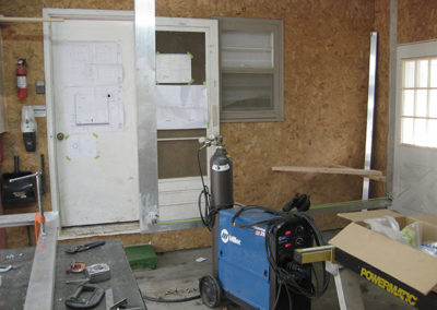
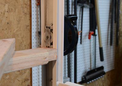
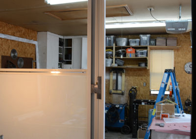
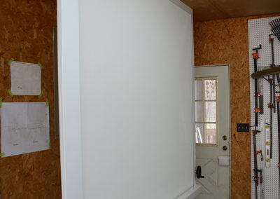
By installing the apparatus to the shop ceiling I was able to simulate the conditions once installed. This proved very key. Notice the 2×4 wood bracing at the right corner where the crank mechanism will be.
Integrated Bottom Up Shade: Finished Frame Back from Paint
Flash forward quite a bit in our process and you can see the finished frame back from paint and the shade installed. You can see an obround hole that allows installation of the shade hem bar to the moving carriage. It also allows for easy adjustment of the shade to align it perfectly parallel with the shade tube.
Integrated Bottom Up Shade: Rearview
Here is a view of the roller shade installed and fed into the moving carriage that moves up and down in the side tracks. The carriages were machined from nylon. The drive cable passes through the carriages and is held securely in position with two set screws.
Integrated Bottom Up Shade: Guide Tube
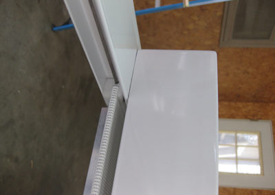
A shot of the entire width of the shade. Notice the little tab sticking up in the middle which is welded to the shade guide tube. This tab is attached to the shade valence and functions to prevent the shade tube from bowing. It had to be stiff along its length to keep the shade tight and wrinkle free. It worked perfectly.
Integrated Bottom Up Shade: Valence Application
Here the shade valences are being fabricated. These were fairly straight forward.
Integrated Bottom Up Shade: Valence Installed
A look at the finished corner with the shade valence installed.
Integrated Bottom Up Shade: Track & Carriage
Another view downward at the track and the carriage where the shade is fed in from the bottom. You can see the aluminum stiffener that runs along the backside of the shade hem bar and keeps it stiff.
Integrated Bottom Up Shade: Valenced Secured to Shade Brackets
From the bottom you can really see clearly how the shade guide works in relation to the roller tube and how the valence is secured to the shade brackets.
Integrated Bottom Up Shade: Drive Mechanism
The drive mechanism was the trickiest challenge of this project. I went through a few trials on this design. To begin with we used a heavy gauge nylon coated aviation cable that was looped around the sides and bottom and back again connecting to both sides of shade hem bar. At first I thought the cable could just loop around the drive wheel but it turns out that wrapping the cable 360 degrees around the drive wheel does not work at all because the portion of cable entering the wheel and the portion exiting always bind on one another. The solution was not obvious but turned out to be simple. A second idler pulley was installed so that the drive wheel only contacts 180 degrees of the cable and therefore cannot bind on itself. The downside was that ½ of the contact on the drive wheel meant half of the friction to grab the cable. The final design of the drive wheel quickly became the heart of the project.
Integrated Bottom Up Shade: Final Drive Wheel
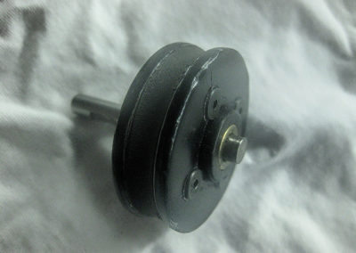
Here is the final drive wheel. It was actually made of about a dozen parts. Complicated yes but very effective. The key to the design was using a low durometer rubber for the contact area and machining it so that it was concave. This design would get as much high friction material around the cable as was feasible. The rubber doughnut was sandwiched between two thick metal washers that were clamped together by four screws. Within that assembly was a very special nylon wheel/bearing assembly that set screwed to the drive shaft and the washer and rubber doughnut assembly anchored to it.
Integrated Bottom Up Shade: Weight Counterbalance
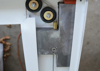
The 6 pound led weight counterbalanced the weight of the shade and the force exerted by the retraction spring. There was indeed a sweet spot for the mass of this weight because the force downward exerted by the shade and the retraction spring was dynamic increasing as the shade was unrolled. Without this counterbalance system there was no way that the cable and drive wheel combination would of worked. The forces would have been too great. Also the compactness of the frame design meant that the weight had to be notched around the pulleys in order to get the amount of travel we needed from the drive assembly.
Integrated Bottom Up Shade: Counterbalance Weight & Raceway
This pic shows the lead counterbalance weight and the raceway that it rides in. The outer guide track is attached to the frame at the top by a screw. By removing the screw you can flex the guide track just enough to get the weight out. The final weight was wrapped in felt so that it was silent going up and down. You can see the cable ends and how they attach to the lead weight. I got my wings clipped on machining lead. It is super soft but workable. The brass turnbuckle engages a threaded rod epoxied into a deep hole in the weight. This allowed the cable to be attached and then tensioned up to about an inch. The slotted connector on the bottom was critical because set screws do not work in lead. This design has the cable set into a small rod and that rod is slipped into a cavity in the weight preventing it form pulling out. Worked like a charm. Notice the rubber bumpers at the top. Also notice how the cable enters the side channels to engage the shade.
Integrated Bottom Up Shade: Weight Raceway
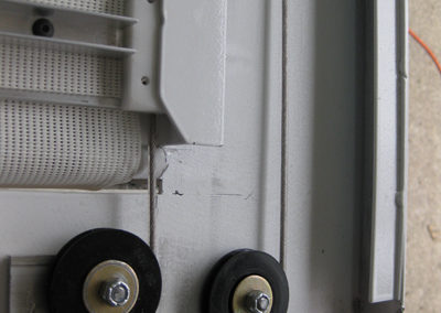
A view at the base of the weight raceway and how the cable enters the channel at the bottom.
Integrated Bottom Up Shade: Client Residence Installation
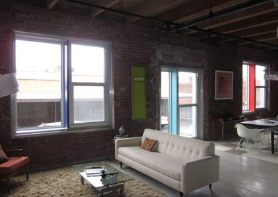
Here is a before shot of the loft. A great view if you like looking at a parking lot. That was the entire reason for the bottom-up design because otherwise the view of the buildings at the top was just great.
